Engineering Dictionary of Terms
"A",
"B",
"C",
"D",
"E",
"F",
"G",
"H",
"I",
"J",
"K",
"L",
"M",
"N",
"O",
"P",
"Q",
"R",
"S",
"T",
"U",
"V",
"W",
"X",
"Y",
"Z"
Audio Amplifier
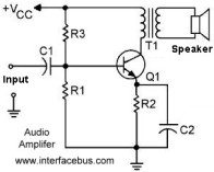
An amplifier designed to amplify frequencies between 15 hertz (15 Hz) and 20 kilohertz (20 kHz), which relates to the frequency range of human hearing. Voice bandwidth on a phone line is limited to between 300Hz and 3.4KHz. The transistor Q1 is the amplifier in the circuit below. All of the examples used here show a NPN transistor in a Common Emitter configuration.
The components selected during design determine if the amplifier is an audio amplifier. A general purpose 2N2222 NPN Transistor would work as a small signal audio amplifier. The 2N2222 will normally be available in either a TO-18 Metal Can, or TO-92 Plastic Package, depending on the desired temperature characteristics. |
 Audio Amplifier |
Any transistor will operate in the audio frequency range. However the transistor should be selected so that it only operates in the audio range. That is any additional bandwidth, which is being unused, could only cause problems for the circuit.

Speaker Amplifier
An audio transformer could be added to allow the circuit to drive a speaker. An Audio Transformer is designed to operate with the lower frequencies found in the audio band. The transformer also serves to block any DC voltage from the supply voltage from reaching the speaker. A steady DC signal would not convey any information and could not cause the speaker to vibrate producing any sound.
Component Functions
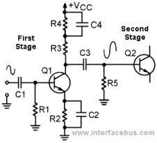
DC Blocking Capacitor; C1 in both schematics function as a DC blocking capacitor. The capacitor blocks any DC bias from a previous stage, so the audio signal is centered around ground [or zero volts]. The capacitor should be selected so that it passes all frequencies between 15Hz and 20kHz. C3, used in one of the circuits is also a DC blocking capacitor and used to isolate the stage from the next amplifier in the chain. For example C3 would be the C1 of the next chain if the two circuit diagrams were connected together, as in the Cascaded Audio Amplifier shown to the right. The transformer used in one of the examples also block any DC, so a DC blocking capacitor is not required after that particular transistor.
Bias Bypass Capacitor; Capacitor C2 is used to by-pass bias resistor R2. The resistor is used to provide a DC bias to transistor to center the operating point of the transistor. However the resistor is taken out of the circuit [by-passed] for the AC audio signal. With resistor R2 removed the audio signal is no longer attenuated, if the capacitor was not present.
By-Pass Capacitor; Any active component should always have their voltage supply line filtered, to ground, using a by-pass capacitor. In many cases the capacitor is not shown on the same page as the circuit that it goes with to save space and not clutter the circuit diagram. With transistor circuits the capacitor is used to by-pass or filter the voltage line being used by the transistor, even though the power rail might not directly connect to the transistor [because of a bias resistor]. Unlike the other capacitors which function in the audio range a filtering capacitor between power and ground is selected to filter higher frequencies.
Bias Resistors; All of the example resistors used in each of the circuits are used to bias the transistor. The value of the resistors depend on their usage [the placement within the circuit], the transistor used and the supply voltage used. The bias resistors position the transistor in the center of its operating range.
Resistor Designations; The schematic segments used on this page use number designations, but letter designations are more commonly used when describing transistors. Resistor R1 is the Base Resistor [Rb] and is used to set the Base current. Resistor R2 fixes the Emitter current of the transistor [Re]. The Collector current is set by resistors R3 and R4 [Rc], although in one case R3 is a Base resistor.
Transistor Amplifier; The transistor is selected for it's gain, collector current, applied voltage and so on. Usually transistors categorized as general purpose can function as small signal amplifiers, as well as transistors categorized as a small signal device. Transistors used to drive speakers or the final output stage would be called large signal or high power transistors.
Related Audio Circuit Diagrams;
Op-Amp Mono Amplifier
Op-Amp Stereo Amplifier
Audio Base Adjustment Circuit. [Low frequency control]
Treble Adjustment Circuit. [High frequency control]
Tone Control Circuit. [instead of a base and treble control]
Midrange Adjustment Control [instead of a base and treble control]
Loudness Switch Circuit [in addition to or instead of a base control]
Speaker Crossover Network [for a multi-speaker driver]


