2N6193 PNP Transistor
2N6193 Temperature-Power Derating Curve
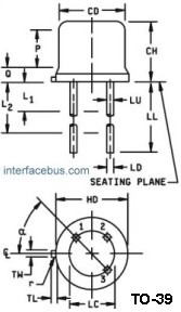
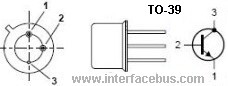
PNP High Power Transistor. Package, TO-39.
2N6193 Applications; High power switching, power amplifier, wide band amplifiers

2N6193 Temperature Derating Curve
The chart indicates the maximum power dissipation with increasing ambient temperature. Maximum operational power dissipation is achievable at 250C. However above 25C the maximum package dissipation, or power, must be reduce to insure that the devices junction temperature remains constant. The higher the ambient temperature is increased the lower the allowable power dissipation, as depicted in the curves.
This particular graph depicts the derating of a 2N6193 transistor in a TO-39 package. Consider incorporating forced air cooling or attaching the device to a metal heat sink to increase the operational range.
Case Derating Equation; 5.71mW/0C above 250C.
Ambient air Derating Equation; 5.71mW/0C above 250C.
Refer to MIL-PRF-19500/561; Semiconductor Device, Transistor, PNP, Switching, Types 2N6193 and 2N6193U3, JAN, JANTX, JANTXV, JANS, JANHC, AND JANKC, [TO-39, U3]
2N6193 Maximum Operation Ratings:
Collector Emitter Voltage = 100 volts dc [Vceo]
Emitter Base Voltage = 6.0 volts dc [Vebo]
Collector Base Voltage = 100 volts dc [Vcbo]
Collector Current = 5.0 Amps dc [Ic]
Power Dissipation = 17.5.0 Watts [Case Temperature 250C]
Power Dissipation = 1 Watt [Ambient Temperature 250C]
Operating Junction Temperature = -65 to +2000C [Tj]
Storage Temperature = -65 to +2000C [Tstg]
Complementary BJT to a 2N5002 and 2N5004 device [How to derate a 2N5002 BJT]
Derating is the method of decreasing a devices operational limits as temperature is increased, in this case derating a devices operational power dissipation vs increasing ambient temperature.
Ambient temperature. is the air temperature measured below a semiconductor device,
in an environment of substantially uniform temperature [Still-Air], cooled only by natural air convection [Free-Air], and not materially affected by reflective and radiant surfaces. Near-by devices that may induce heat onto this device are not accounted for in any derating curve, and omitted during the actual testing to develop the curves. In general; ambient air is the air surrounding a device, and the curves may not specify the location the temperature of the air was taken at. The rule would be to take the temperature at the same time and same location near the device for each test run, assuming more than one test is performed.
Case mount. A type of package which provides a method of attaching one surface of the
semiconductor device to a heat sink to achieve thermal management of the case temperature. This part and the package it reside in is not considered a case-mount part. The 2N6193, or more correctly the TO-39 package is mounted via its three terminals. In some limited cases the terminals are taken all the way down to the printed wiring board [PCB], allowing the case to make content with the PCB; but, usually a plastic spacer is used between the board and component. In any case, the only way to make this package style a case-mount part is to drill a large hole into the PCB and mount this device upside down, with the metal can inserted into and through the board. Mounting a TO-39 up-side down is called Embedded Mounting, and is used only in high vibration environments.
Case temperature. is that temperature measured at a specified point on the case of a
semiconductor device. Some Temperature-Power derating curves show maximum power by ambient temperature [Ta] while some show maximum power by case temperature [Tc], the two curves are entirely different. Attaching a device to a heat sink greatly reduces the requirement to derate the device over temperature.
Temperature coefficient. The ratio of the change in a parameter to the change in temperature.
Thermal resistance. Thermal resistance is the temperature rise, per unit power dissipation, of a junction
above the temperature of a stated external reference point under conditions of thermal equilibrium. Check the derating curves for Thermal resistance.