2N3791 Temperature-Power Derating Curve [2N3792]
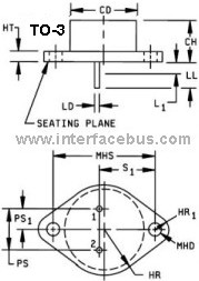
PNP High Power Transistor. Package, TO-3 metal Can.

Temperature Derating Curve, 2N3791 Transistor
Use the Graph to determine maximum operating power [wattage] based on device case temperature. Derating Curves Transistors
The graph details the maximum allowable power dissipation with increasing ambient temperature. Maximum operational power dissipation is achievable at 25C. The not-to-exceed junction temperature is 2000C
Refer to MIL-PRF-19500/379; Semiconductor Device, Transistor, PNP, Silicon, High-Power, Types 2N3791 and 2N3792, JAN, JANTX, JANTXV, and JANS, [TO-3 package]
2N3791 Maximum Operational Ratings:
Collector Emitter Voltage = 60 volts dc
Collector Base Voltage = 60 volts dc
Emitter Base Voltage = 7 volts dc
Base Current = 4 amps dc
Collector Current = 10 amps dc
Power Dissipation 250C [Air] = 5 Watts
Power Dissipation 1000C [Case] = 85.7 Watts
Operating Temperature = -65 to +2000C
Refer to the data sheet for additional electrical characteristics.
Heat Sink Manufacturers, Listing of Transistor Manufacturers
Case mount. A type of package which provides a method of readily attaching one surface of the
semiconductor device to a heat dissipater to achieve thermal management of the case temperature. The Collector is electrically connected to the case in a TO-3 package.
Replacement Information; MIL-PRF-19500/621 is a TO-254 package version of MIL-PRF-19500/379, which is a TO-3 package version. The military 2N7369 contains the same die as the military 2N3792. The MIL-PRF-19500/621 is preferred over the MIL-PRF-19500/379 whenever interchangeability is not a problem. For new design use 2N7369. The 2N3792 is inactive for new design. Transistor types 2N3789 and 2N3790 were deleted by MIL-PRF-19500/379A(ER).
Editor note: I'm not sure I follow this recommendation at all. The two transistor packages are completely different. How can you recommend a replacement when the package is not even near the same, regardless of having the same semiconductor die. Although the fact that the two part number have the same semiconductor die is a good starting point, it reduces the time required to redesign a circuit to almost zero. But the implication that these two transistors can be or are drop-in replacement is a bit hard to understand. Just trying to insert a TO-254 device into the foot-print of a TO-3 has me wondering, what about the missing third lead of the TO-3. The TO-254 is installed into the two terminal hole of the TO-3 and than the third lead is folded over to one of the flange holes for attachment.
I have to assume I'm interrupting the recommendation wrong. In any event, this page cover the derating of a 2N3791 in a TO-3 package. It does not cover the the identical semiconductor die in a completely different package, regardless of the fact of using the same die. But on a side note, the statement about the other transistor being preferred should be taken very seriously when a new design is being under taken. In fact this component should not even be considered for a new design, given the long design times incurred by some military systems. That is, this part could go obsolete before a new system is even fielded, so why take the chance. Than there's the entire length of time the system might stay in the field before it's up-graded. So why start with a part that has any chance of going obsolete, and having to purchases ten years worth of spare parts to make up for the fact that it went obsolete.
When to Derate; Derating Guidelines for Electronics
Engineering Recommendation: When possible never use a part that has a chance of going obsolete. However designers should also use caution when using parts that have just entered the market, or are still preliminary. As these parts could also disappear quickly if the manufacturer determines there is no market for the devices, or they are to costly to produce for the intended market.