2N3715 Temperature-Power Derating Curves
NPN High-Power Transistor. Package, TO-3 metal Can.
2N3715 Applications; Medium speed switching and amplifier circuits

2N3715 Transistor Operational Power Derating Curve
The chart gives the maximum allowable package power dissipation with increasing temperature. Maximum operational DC power dissipation is achievable only at 25C. However above 25C the maximum package dissipation, must be reduce to insure that the devices junction temperature remains constant. The higher the ambient temperature is increased the lower the allowable power dissipation, as shown in the curves [although Case Temperature is used].
Decreasing a devices operational limits as temperature is increased is called derating, in this case derating a devices operational power dissipation vs increasing ambient temperature. Derate linearly 28.57mW/0C for an ambient temperature above 250C with still air. Apply forced air to the system to increase the operational temperature range. Attaching the 2N3715 to a metal plate, using a metal washer, thermal grease or attaching a heat sink will all lower case temperature.
Transistor Derating Curves [by device number], with terms and definitions.
Refer to MIL-PRF-19500/408; Semiconductor Device, Transistor, NPN, Silicon, High-Power, Types 2N3715 and 2N3716, JAN, JANTX, JANTXV, and JANS, [TO-3 package]
2N3715 Maximum Operational Ratings:
VCEO Collector Emitter Voltage = 60 volts dc [2N3715]
VCEO Collector Emitter Voltage = 80 volts dc [2N3716]
VCBO Collector Base Voltage = 80 volts dc [2N3715]
VCBO Collector Base Voltage = 100 volts dc [2N3716]
VEBO Emitter Base Voltage = 7 volts dc [2N3715, 2N3716]
IB Base Current = 4A dc [2N3715, 2N3716]
IC Current Current = 10A dc [2N3715, 2N3716]
Power Dissipation 250C = 5 Watts [2N3715, 2N3716]
Operating Temperature = -65 to +2000C
Storage Temperature = -65 to +2000C
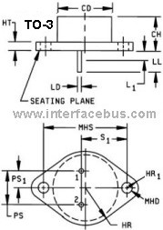
TO-3 Pin Out: Lead 1 = emitter, lead 2 = base, lead 3 = collector.
The collector is electrically connected to the case. TO-3 Case Dimensions.
The standard defines the 2N3715 as a medium switching transistor, which means that this component may be used in applications that depend on the switching speed of the device. The amount of time it takes from the output of the 2N3715 to rise from a low voltage to a high voltage after receiving an input is defined as 1.3uS [Pulse Rise Time]. While the amount of time it take from the output of the 2N3715 to fall from a high voltage to a low voltage after receiving an input is defined as 1.2uS [Pulse Fall Time]. The pulse delay time is given as 0.2uS.


