Electrical Engineering Dictionary
"A"
"B"
"C",
"D",
"E",
"F",
"G",
"H",
"I",
"J",
"K",
"L",
"M",
"N",
"O",
"P",
"Q",
"R",
"S",
"T",
"U",
"V",
"W",
"X",
"Y",
"Z"
Active High-Pass Filter
This design of a active high-pass filter follows in the same general configuration of the Active Low-Pass Filter circuit, although the component placement has changed in order for the circuit to function as a high-pass filter. This particular circuit uses the LM833 operational amplifier. The LM833 is a dual Op-Amp package, although only one amplifier is being used here, and is designed for the audio range [for audio components or gear].

LM324 Low-Pass Filter
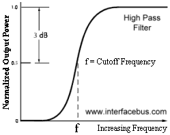
High-Pass Filter Design
The circuit is configured with a gain of two, just like the previous circuit. The gain of the non-inverting amplifier is determined by; Av = 1 + Rf/Ri [with the ratio of Rf to Ri equal to 1]. To configure the circuit to a unity gain amplifier remove resistors Rf & Ri and directly connect the output of the amplifier to the minus input [short out Rf].
The circuit is also configured as a second order high-pass filter, which is determined by resistors R1 & R2, and capacitors C1 & C2. The second-order high pass provides for a 40dB/decade down in signal [or attenuation] below the cut-off frequency of the filter. The circuit could easily be made into a first-order high pass, with a 20dB/decade slope, by removing C1 and R1 without effecting the cut-off frequency of the filter.
The circuit design approach follow the previous example, beginning with selecting the cut-off frequency and choosing an appropriate capacitor for that frequency. The resistor are than calculated using the standard formula; 1.414 / (2 * 2 * 3.14 * f * C). Using the component values shown in the circuit the cut-off frequency results in about 1kHz.
A more precise frequency could be obtained by using 1 percent Standard Resistor Values, rather than 5 percent values, but the deviation of the capacitor value because of tolerance would also have to be accounted for.
This once again this is a Butterworth filter with a flat pass-band, other filter types such as a Bessel or Chebyshev would require different values and a different design approach to come up with those values. Although the circuit layout or component placement would remain the same regardless of the filter type, only the component values would change.