Technical Engineering Definitions
"A"
"B"
"C",
"D",
"E",
"F",
"G",
"H",
"I",
"J",
"K",
"L",
"M",
"N",
"O",
"P",
"Q",
"R",
"S",
"T",
"U",
"V",
"W",
"X",
"Y",
"Z"
Pulse Duration Modulation
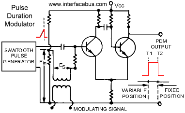
Pulse Duration Modulation [PDM] is a type of pulse modulation in which the time duration of the pulses is changed by the modulating signal. Which is the same thing as Pulse Width Modulation [PWM]. In both cases the pulse width or pulse duration of the pulse is varied by the modulating voltage. The circuit below shows one possible example.
The circuit is a One-shot Multivibrator [Monostable Multivibrator Defined]. However the circuit differs from the standard Transistor Monostable Multivibrator in that there are two inputs. Although the sawtooth pulse, Ein, could be considered the bias voltage [Vbb] found in the standard transistor one-shot circuit.
Pulse Duration Modulation
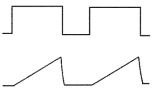
This circuit uses a Sawtooth Pulse Generator to develop the DC bias voltage [Ein] on the Base of the first transistor. The waveform is composed of a linear ramp followed by a steep drop back to its initial state. The sawtooth is applied directly to the Base circuit through a DC blocking capacitor.
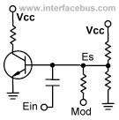
The modulating signal is also applied to the Base circuit, through a transformer. The voltage [Es] is developed across the secondary side of the transformer. An alternate view of the input connection is shown in the side-bar, so that it corresponds to the standard drawing of a monostable multivibrator.
The rest of the circuit corresponds to the standard circuit configuration, except for the output transistor connection. In a normal circuit the first transistor receives a feedback voltage to its Base terminal from the Collector of the output transistor. This feedback signal is not needed [or replaced] by the bias voltage of the modulating signal.
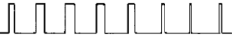
The output signal is a pulse which has a fixed position in time which is related to the following edge of the sawtooth. The falling edge of the output pulse T2 is fixed and occurs at the same periodic rate as the sawtooth pulse. Each time the input pulse terminates [returns to zero], the output pulse also terminates. So the output pulse trains follow the input pulse train and occurs at the same rate. However the duty cycle [pulse duration] of the output pulses changes as the input to the circuit changes. This circuit is a One-shot, so for the circuit to produce a re-occurring pulse train, a continuous stream of trigger pulses needs to be applied. Otherwise one input trigger pulse will result in a single output pulse.
The leading edge [marked as variable position], T1 is generated by the changing bias voltage on the input Base circuit. The modulating signal is superimposed on the input bias voltage. As the bias voltage is varied the input triggers and produces an output, but when the input pulse goes to zero the transistor is turned off [regardless of the condition of the modulating signal].
An alternative approach would be to reverse the direction of the incoming sawtooth wave [rapid rise followed by falling slope]. This change would fix the rising edge of the output [T1] and cause the trailing edge [T2] to vary in time. However the circuit would still be the same pulse duration circuit it was before.