Technical Radar Terms
"A",
"B",
"C",
"D",
"E",
"F",
"G",
"H",
"I",
"J",
"K",
"L",
"M",
"N",
"O",
"P",
"Q",
"R",
"S",
"T",
"U",
"V",
"W",
"X",
"Y",
"Z"
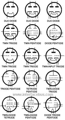
Classification of Electron Tubes
1. Beam Switching
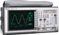
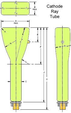
2. Cathode Ray [CRT Terms and Definitions]
--- a. Electrostatic or Magnetic Focus
--- b. Electrostatic or Magnetic Deflection
--- c. Multi-gun (specify number of guns)
3. Cathode-Ray Charge Storage
--- a. Visual Output (direct view)
--- b. Electrical Output
4. Cold Cathode
--- a. Triode
--- b. Rectifier
5. Corona Voltage Regulators
6. Cross Field Amplifier
7. Electron Multiplier
8. Electron Ray Indicator
9. Gas-Switching
--- a. ATR (anti-transmit-receive)
--- b. Dual-TR (transmit-receive)
--- c. Pre-TR
--- d. TR
10. Graphic Indicator Numerical Indicator
11. Gyrotron
12. Ignitron
13. Image Converter
14. Image Orthicon
15. Klystron
--- a. Reflex Oscillator
--- b. Amplifier
--- c. Pulse
--- d. Continuous Wave (CW)
16. Magnetron
--- a. Pulse
--- b. Coaxial
--- c. Continuous Wave (CW)
--- d. Voltage Tunable
17. M-Type Backward Wave
18. Negative Grid (microwave)
19. Noise Source
--- a. Vacuum Diode Geiger Mueller
--- b. Gas Discharge
20. O-Type Backward Wave
21. Phototube
--- a. Gas
--- b. Infrared
--- c. Multiplier
--- d. Vacuum
22. Power or Transmitting
--- a. Diode [Diode Tube Definition]
--- b. Triode [Triode Tube Definition]
--- c. Tetrode [Tetrode Tube Definition]
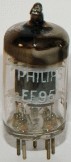
--- d. Pentode [Pentode Tube Definition; EL84, EF95, 6AK5]
--- e. Rectifier
23. Pulse Modulator
--- a. Hydrogen
--- b. Vacuum Glow Discharge
24. Radiation Counter
--- a. Geiger Mueller
25. Receiving
--- a. Diode
--- b. Triode
--- c. Tetrode
--- d. Pentode
--- e. Rectifier
--- f. Power
26. Stabilotron
27. Thyratron [Thyratron Tube Definition]
28. Traveling Wave (or forward wave)
29. Vidicon
30. Voltage Regulator
Microwave Tubes. Tubes utilizing principles of operation that are normally employed at frequencies above one gigahertz, or tubes using distributed rather than lumped circuit elements.
Miniature Tubes. Tubes with shape and dimensions designated in EIA 209 as T5-1/2 and T6-1/2 (round) envelope configuration and rigid pins.
Power Tube. Tubes so designated by the TSS. These are negative grid tubes normally operated as oscillators, amplifiers, or drivers with an anode dissipation, generally of 50 watts (formerly this was 25 watts) or more per tube. These also include rectifiers with rectified power output generally of 250 watts or more.
Receiving Tubes. Tubes so designated by the TSS. These are negative grid tubes normally operated as oscillators, amplifiers, mixers, or converters with an anode dissipation of under 50 watts (formerly this was 25 watts). These also include diodes or rectifiers with rectified power output under 250 watts.
RGK. The symbol used to express the resistance between the grid and the cathode of an electron tube.
Subminiature Tubes. Tubes with shape and dimensions designated in EIA 209 as T2x3 (oval) and T3 (round) envelope configuration and flexible wire leads.
Transmitting Tubes. Tubes so designated by the TSS. These are negative grid tubes normally operated as oscillators, amplifiers, or drivers with an anode dissipation, generally of 50 watts (formerly this was 25 watts) or more per tube. These also include rectifiers with rectified power output generally of 250 watts or more.
Heat Shield. A vacuum tube may require a heat shield to dissipate additional heat. The heat shield is placed over the vacuum tube and attached to the base or tube socket. The heat shield may also have an internal spring to securely attach the vacuum tube to the socket and provide good contact to the tube. |
 Heat Shield |
Refer here for CRT Manufacturers, Cathode-ray Tube Vendors