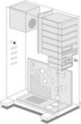

Chassis Power Distribution
Design Notes
The Metal chassis should be effectively bonded to a main grounding point
in the rack cabinet where necessary to assure electrical continuity
and
shall have the capacity to conduct safely any fault current likely to be
imposed on it. Also refer to Rack Grounding design notes.
Chassis to Rack grounding may be bare copper wire insulated green wire or ground straps.
In a chassis with ac service connected to it, the grounding terminal of
its receptacle shall be internally bonded to the chassis frame.
If solder
is used, the connection of the equipment grounding conductor shall not
depend on solder alone. Also refer to Chassis Grounding design tips.
Input/output ac power connections to the chassis shall comply with NEC
requirements. Reference AC Power Inlet Connector Manufacturers.
Plugs and sockets for connecting any AC power source shall be NRTL
[Nationally Recognized Testing Laboratory] approved for the
application.
AC power plugs and sockets shall not be used for purposes other than the
connection of AC power.
Connectors operating at 50 V or greater shall be rated or recommended for
their intended use.
Any connector used to provide power at 50 V or greater shall not allow
personnel to make inadvertent contact with the power source.
If plug pins of cord-connected equipment receive a charge from an
internal capacitor, the pins shall not be capable of rendering an
electric shock or electric burn in the normal or the single fault
condition 5 seconds after disconnection of the supply.
Plug-in type connectors intended to be connected and disconnected by hand
shall be designed so that the grounding conductor connection makes first
and breaks last with respect to the other connections.
All terminals/live parts with a potential of 50 volts or greater shall be
guarded to protect from accidental contact or bringing conductive objects
in contact with them.
All enclosures containing exposed energized circuits over 600 volts
nominal should be marked, with a label that is permanent;
Danger High Voltage Keep Out. Also see Equipment Safety Markings design tips.
The exposed, non-current carrying, metal parts of panel mount connectors
operating at 50 volts or greater shall be bonded to the chassis.

How to Chassis Design, and Chassis Manufacturers
EIA-310-D Cabinets, Racks, Panels, and Associated Equipment
IEC 60297-1 Mechanics for Racks - 19 inch common standard
(DIN41494)
IEC 297-x Dimensions of Panels and Racks
MIL-STD-901D SHOCK TESTS. H.I. (HIGH-IMPACT)
SHIPBOARD MACHINERY, EQUIPMENT, AND SYSTEMS, REQUIREMENTS FOR
[Shock]
MIL-STD-167-1 MECHANICAL VIBRATIONS OF SHIPBOARD EQUIPMENT (TYPE 1
- ENVIRONMENTAL AND TYPE II - INTERNALLY EXCITED) [Vibration]
MIL-STD-5400 ELECTRONIC EQUIPMENT, AEROSPACE, GENERAL
SPECIFICATION FOR [See MIL-HDBK-5400]
MIL-STD-810E ENVIRONMENTAL ENGINEERING CONSIDERATIONS AND
LABORATORY TESTS [Humidity]
MIL-STD-46IE REQUIREMENTS FOR THE CONTROL OF ELECTROMAGNETIC
INTERFERENCE CHARACTERISTICS OF SUBSYSTEMS AND EQUIPMENT [EMI/EMC]
MIL-STD-462 Measurement of Electromagnetic Interference
Characteristics of Subsystems and Equipment [EMI/EMC]
MIL-STD-704F AIRCRAFT ELECTRIC POWER CHARACTERISTICS
MIL-STD-1275B CHARACTERISTICS OF 28 VOLT DC ELECTRICAL SYSTEMS IN
MILITARY VEHICLES
MIL-A-8625A - Anodic Coatings for Aluminum and Aluminum
Alloys
MIL-C-5541E - Chemical Conversion Coatings for Aluminum and
Aluminum Alloys
Chassis Height is also given in 'U', 1U = 44.45mm,
2U = 88.90mm, and so on.
Chassis Width may be given in 'HP', 1HP = 5.08mm
(0.2in). HP ~ Horizontal Pitch.

Editor comment; these are design notes based on military standards.
When local municipal codes are required, they should prevail.
 | |||||||
| Home | |||||||
 |
 |
 |
 |
 |
 |
 |
 |
| Distributors | Components | Equipment | Software | Standards | Buses | Design | Reference |